NMT Half-Centre Oscillator
Two ionic neurons with reciprocal voltage-driven inhibition, implementing Task 2 of the Neuromorphic Toolbox proposal.
Abstract
Task 2 of the Neuromorphic Toolbox proposal (P23) asks us to couple two sodium/potassium neurons through reciprocal graded inhibition, apply an asymmetric current onset and compare their voltages and spike times with Toolbox reference traces.
Results
Response to asymmetric current onset
Neuron 1 produces 20 spikes and neuron 2 produces 20 spikes during the 200 ms recording. After equal drive begins at 10 ms, their recorded spike events alternate. Figure 1 shows the voltages, reciprocal inhibition and joint voltage trajectory.
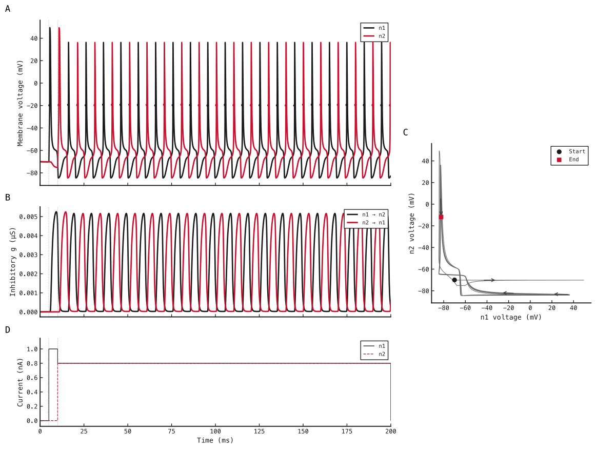
A: membrane voltage and sampled upward −20 mV crossings for n1 in black and n2 in red. B: inhibitory conductance n1→n2 in black and n2→n1 in red; colour identifies the source neuron. C: n2 voltage against n1 voltage over the same 200 ms, in grey, with direction arrows, a black start dot and a red end square. D: injected currents, n1 solid black and n2 dashed red; equal currents overlap after 10 ms. Dotted lines mark the 5 ms kick onset and 10 ms equal-drive onset. States are sampled after each 0.001 ms step; initial values are added at zero for display. nF/µS/nA are a consistent unit convention for the proposal’s numerical values, whose capacitance, conductance and current units are unstated.
Methods
1. Couple the proposal’s ionic neurons with graded inhibition
Each cell uses the Task 1 ionic model. For neuron index and channel ,
Here is time in ms, is membrane voltage in mV, is filtered voltage in mV, is the channel time constant in ms, and are channel and maximum conductance in µS, is the sigmoid slope in mV, and is its midpoint in mV. The argument is dimensionless.
For the graded synapse from neuron to neuron , with ,
Here is the synaptic gate voltage in mV, its time constant in ms, and the synaptic and maximum conductance in µS, the slope in mV and the midpoint in mV. The membrane equation gains the inhibitory conductance term:
Here is capacitance in nF, injected current in nA, leak conductance in µS, and , , and are leak, sodium, potassium and inhibitory reversal potentials in mV. These units preserve the proposal’s numerical equations; its C/g/I units require confirmation against the Toolbox.
At every step of length ms, all ionic and synaptic gates advance by forward Euler using the preceding membrane voltages. New gate values determine conductances; both membranes then advance using those new conductances and the old voltages. The cells have no voltage reset.
2. Represent both synapses as native graph connections
SNNLab 0.24 lets a custom synapse declare input_unit="mV" and
output_unit="uS". Each projection reads pre.voltage at the beginning of
the timestep and delivers the newly updated conductance to post.inhibitory.
Dimensionless projection weights are one; the physical maximum conductance
belongs inside the synapse, after the nonlinear gate. Zero added delay avoids
shifting the proposal’s coupling by an extra timestep.
The following callback implementation is loaded directly from this experiment:
import torch


def neuron_initial_state(ctx):
    voltage = torch.full(
        ctx.shape, ctx.config["initial_voltage_mv"], device=ctx.device, dtype=ctx.dtype
    )
    return dict(
        voltage=voltage,
        z_na=voltage.clone(),
        z_k=voltage.clone(),
        current=torch.zeros_like(voltage),
        step_index=torch.zeros(ctx.shape, device=ctx.device, dtype=torch.int64),
    )


def neuron_step(ctx):
    cfg, state, dt = ctx.config, ctx.state, ctx.dt_ms
    voltage = state["voltage"]
    z_na = state["z_na"] + dt / cfg["tau_na_ms"] * (voltage - state["z_na"])
    z_k = state["z_k"] + dt / cfg["tau_k_ms"] * (voltage - state["z_k"])
    g_na = cfg["g_na_us"] * torch.sigmoid(
        cfg["gamma_na_per_mv"] * (z_na - cfg["bias_na_mv"])
    )
    g_k = cfg["g_k_us"] * torch.sigmoid(
        cfg["gamma_k_per_mv"] * (z_k - cfg["bias_k_mv"])
    )
    # Use integer intervals so current changes exactly at 5 and 10 ms.
    index = state["step_index"]
    current = torch.where(
        (index >= cfg["kick_start_step"]) & (index < cfg["kick_stop_step"]),
        torch.full_like(voltage, cfg["kick_na"]),
        torch.where(
            index >= cfg["drive_start_step"],
            torch.full_like(voltage, cfg["drive_na"]),
            torch.zeros_like(voltage),
        ),
    )
    outward = (
        cfg["leak_us"] * (voltage - cfg["leak_reversal_mv"])
        + g_na * (voltage - cfg["e_na_mv"])
        + g_k * (voltage - cfg["e_k_mv"])
        + ctx.inhibitory * (voltage - cfg["synapse_reversal_mv"])
    )
    updated = voltage + dt / cfg["capacitance_nf"] * (current - outward)
    spikes = (
        (voltage < cfg["spike_threshold_mv"]) & (updated >= cfg["spike_threshold_mv"])
    ).to(voltage.dtype)
    return {
        **state,
        "voltage": updated,
        "z_na": z_na,
        "z_k": z_k,
        "current": current,
        "step_index": index + 1,
    }, spikes


def synapse_initial_state(ctx):
    gate = torch.full(
        ctx.shape, ctx.config["initial_gate_mv"], device=ctx.device, dtype=ctx.dtype
    )
    value = ctx.config["g_max_us"] * torch.sigmoid(
        ctx.config["gamma_per_mv"] * (gate - ctx.config["bias_mv"])
    )
    return dict(gate=gate, value=value)


def synapse_step(ctx):
    gate = ctx.state["gate"] + ctx.dt_ms / ctx.config["tau_ms"] * (
        ctx.drive - ctx.state["gate"]
    )
    value = ctx.config["g_max_us"] * torch.sigmoid(
        ctx.config["gamma_per_mv"] * (gate - ctx.config["bias_mv"])
    )
    return dict(gate=gate, value=value)
Each neuron declares conductance input ports. Because native custom neuron ports share one input unit, its prescribed injected current is calculated inside the neuron callback from saved schedule parameters and an integer step counter. The counter is retained in native continuation state. This implements the fixed offline protocol; it does not provide an interactive current input.
3. Run one HCO and validate its saved trajectory
Both membrane voltages and every gate start at −70 mV. Neuron 1 receives 1.0 nA for ms, then 0.8 nA; neuron 2 receives 0.8 nA for ms. All other input intervals have zero current. One HCO runs for 200 ms in float64 on CPU; no batch benchmark is performed. Spikes are sampled upward −20 mV crossings, timed at the end of the crossing timestep without interpolation. Strict alternation after 10 ms means every consecutive event belongs to the other cell, with no simultaneous events.
Against independent forward-Euler equations, maximum voltage differences are 1.73e-10 mV for n1 and 1.20e-10 mV for n2. Both cells have matching reference spike counts.
The proposal’s thresholds are maximum voltage difference below 0.1 mV, spike-time difference below 0.05 ms and identical counts for each neuron. Toolbox reference traces have not been supplied, so this comparison establishes agreement with the written equations only.
Network diagram
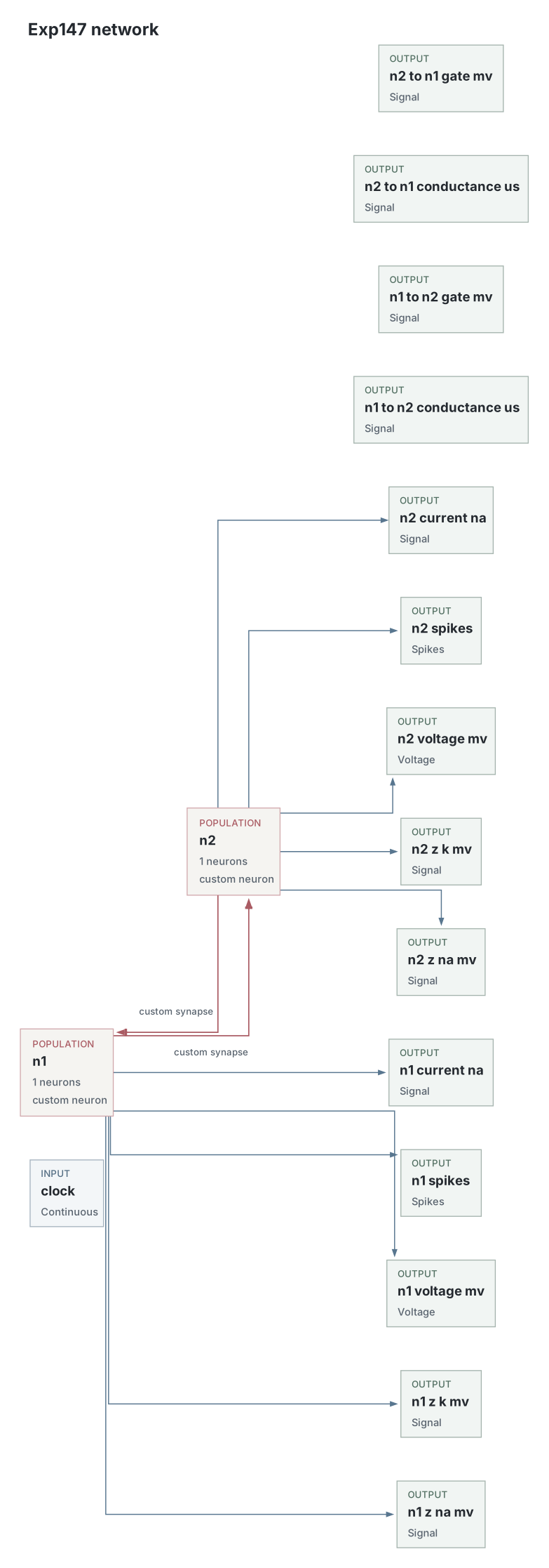
The two voltage-driven projections are explicit graph edges. The unconnected clock input supplies execution axes; fixed current schedules are part of each custom neuron. The circuit is exported from the executed compiled bundle.
Parameters
Both cells share the listed ionic settings, and both synapses share the listed gate settings. Values come from the original native simulation-start snapshot and recorded compute configuration. Na / K denotes sodium / potassium.
| Parameter | Saved value |
|---|---|
| Network | |
| Neurons / reciprocal synapses | 2 / 2 |
| HCOs executed together | 1 |
| Voltage-drive projection weight | 1 |
| Added projection delay (ms) | 0 |
| Neurons | |
| Capacitance (nF) | 0.01 |
| Leak conductance (µS) / reversal (mV) | 0.01 / -70 |
| Na / K maximum conductance (µS) | 1 / 10 |
| Na / K reversal (mV) | 50 / -85 |
| Na / K gate time constant (ms) | 1 / 10 |
| Na / K sigmoid slope (mV⁻¹) | 1 / 1 |
| Na / K sigmoid midpoint (mV) | -60 / -60 |
| Initial membrane and ionic gate voltages (mV) | -70 |
| Observed upward-crossing threshold (mV) | -20 |
| Synapses | |
| Maximum conductance (µS) | 1 |
| Inhibitory reversal potential (mV) | -85 |
| Gate time constant (ms) | 10 |
| Sigmoid slope (mV⁻¹) / midpoint (mV) | 1 / -55 |
| Initial gate voltage (mV) | -70 |
| Input and simulation | |
| Integration | gate-first forward Euler; beginning-of-step voltage sources |
| Timestep / duration (ms) | 0.001 / 200 |
| n1 kick onset / stop (ms) | 5 / 10 |
| n1 kick amplitude (nA) | 1 |
| Equal drive onset (ms) / amplitude (nA) | 10 / 0.8 |
| Device / dtype | cpu / float64 |
| Unit convention | mV, ms, nF, uS, nA; C/g/I units assumed |
| Validation | |
| Voltage tolerance (mV) | 0.1 |
| Spike-time tolerance (ms) | 0.05 |
| Toolbox reference | Toolbox reference traces not supplied |
Dataset
Upstream: —
Downstream: —
| Run | Date | Duration | Size | Evidence | Storage | Ran on | Verification |
|---|---|---|---|---|---|---|---|
| exp147-r003-present | 5s | 549.7 KB | Current | R2 | Local | Local: absent; R2: catalog-verified | |
| exp147-r002-analyse | <1s | 14 MB | Current | R2 | Local | Local: absent; R2: catalog-verified | |
| exp147-r001-compute | 29s | 14.1 MB | Current | R2 | Local | Local: absent; R2: catalog-verified |